Audimodif : A6 4F C6

Caméra de recul
dimanche 13 novembre 2011

Tutoriel en construction
gmail Fernand:
Camera de recul: 4L0 980 551 274.40 ttc
Calculateur camera recul: 4F0 910 441 A 295 ttc
can gateway 4L0 910 441 A ou 4F0 910 441 A 305 ttc
Support calculateur: 4F0 907 297 8 ttc
poignée de coffre: 4L0 827 574 3FZ 75 ttc
Syntoniseur TV -R78- (jusque semaine 35 de 2008) : connecteurs
C - Connecteur multiple à 20 raccords (T20n) rouge
1 - Borne 30
2 - Borne 31
3 - Câble de diagnostic - interruption du circuit à fibres optiques
4 - Masse de blindage
5 - Sortie vidéo (RSE)
6 - Masse de blindage (audio)
7 - Sortie audio côté gauche L (RSE)
8 - Sortie audio côté droit (RSE)
9 - Masse de blindage² Cable noir fil RCA 1
10 - Entrée audio, côté gauche Cable blanc fil RCA 1
11 - Entrée audio, côté droit cable rouge fil RCA 1
12 - Entrée vidéo cable jaune fil RCA 1
13 - Masse de blindage Cable noir fil RCA 1
14 - Masse de blindage
15 - Masse de blindage Cable noir fil RCA 2
16 - Entrée audio, côté gauche Cable blanc fil RCA 2
17 - Entrée audio, côté droit Cable Rouge fil RCA 2
18 - Entrée vidéo Cable jaune fil RCA 2
19 - Masse de blindage cable noir fils RCA 2
20 - ID-PIN
D'après ETKA LG le 23/01/2011:
Modul Calculateur camera recul: 4F0 910 441 A (+ 4L0 907 441A (can gateway ?) attention, remplacé par 4L0 910 441 A, attention, ref pour A6 break= 4F0 910 441 A)
Support calculateur: 4F0 907 297
2 ecrou : N 015 082 13
Connecteur 54 Broches pour modul calulateur: 4E0 972 144
Camera de recul: 4L0 980 551
Joint camera autocollant: 4L0 980 555
Etrier de fixation: 4L0 980 553
Vis: N 909 159 01
Support pour connecteur (coffre) : 1K0 937 545 M
Support (grommet) : 3D0 971 830 F
Fiche douille d'antenne camera: 6Q0 035 576 K
Fiche douille d'antenne camera plat: 1J0 973 119
poignée de coffre: 4L0 827 574 3FZ
Remarques générales
Le système de caméra de recul assiste le conducteur lors des manoeuvres en marche arrière en affichant l'image de la situation de circulation à l'arrière du véhicule via l'unité d'affichage pour calculateur d'unité d'affichage et de commande pour informations, à l'avant -J685-.
Le système se met en marche dès que la marche arrière est engagée. La touche d'aide au stationnement -E266- qui se situe dans la console centrale permet d'activer le système manuellement.
Le système de caméra de recul est constitué des composants suivants :
Caméra de recul -R189-
Calculateur de système de rétrocaméra -J772-
Calculateur d'unité d'affichage et de commande avant du système d'information -J523-
Volant avec capteur d'angle de braquage -G85-
Il est également possible que d'autres calculateurs soient montés.
Le montage d'un support de plaque de police supplémentaire n'est pas autorisé sur les véhicules équipés du système de caméra de recul, car il risque d'entraîner des problèmes de dysfonctionnement du système de caméra de recul.
La recherche des pannes s'effectue via l'« Assistant de dépannage » → système de diagnostic embarqué, de métrologie et d'information VAS 5051.
1 - Interface de diagnostic du bus de données -J533- derrière la boîte à gants
2 - Unité d'affichage pour calculateur d'unité d'affichage et de commande pour informations, à l'avant -J685- au centre du tableau de bord
3 - Calculateur de l'unité d'affichage et de commande avant du système d'information situé derrière la boîte à gants
4 - Unité de commande multimédia -E380- dans la partie inférieure de la console centrale
5 - Câble FBAS reliant le calculateur de système de rétrocaméra -J772- au calculateur d'unité d'affichage et de commande avant du système d'information -J523-
6 - Câble FBAS venant du syntoniseur TV -R78-
7 - Câble FBAS venant de la caméra de recul -R189-
8 - Caméra de recul -R189- dans le hayon
9 - Calculateur de système de rétrocaméra -J772- derrière le revêtement latéral droit du coffre à bagages.
10 - Syntoniseur TV -R78- derrière le revêtement latéral gauche du coffre à bagages
11 - Bus CAN (confort)
12 - Bus MOST
13 - Calculateur d'aide au stationnement -J446- derrière le revêtement latéral droit du coffre à bagages.
14 - Calculateur du réseau de bord -J519- derrière le recouvrement du tableau de commande côté conducteur
15 - Calculateur central de système confort -J393- derrière le revêtement latéral droit du coffre à bagages.
16 - Calculateur d'identification de remorque -J345- derrière le revêtement latéral droit du coffre à bagages.
17 - Calculateur d'accès et d'autorisation de démarrage -J518- derrière le revêtement latéral droit du coffre à bagages.
18 - Calculateur d'ABS -J104- dans le compartiment moteur
19 - Capteur d'angle de braquage -G85- sur la colonne de direction au niveau du calculateur d'électronique de colonne de direction -J527-
20 - Bus CAN (propulsion)
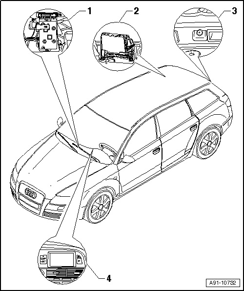
1 - Calculateur d'unité d'affichage et de commande avant du système d'information -J523-
q
Derrière la boîte à gants
2 - Calculateur de système de rétrocaméra -J772-
q
Derrière le revêtement latéral droit du coffre à bagages
q
Affectation des fiches → chap.
q
Dépose et repose → chap.
3 - Caméra de recul -R189-
q
Dans le hayon à côté de la poignée
q
Dépose et repose - Avant → chap.
4 - Afficheur du calculateur de l'unité d'affichage et de commande, système d'information AV -J685-
q
Dans la partie centrale du tableau de bord
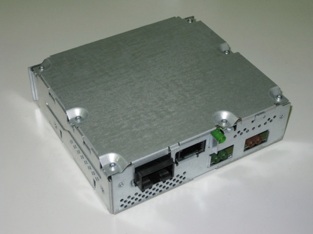
Calculateur de système de rétrocaméra -J772-
A - Connecteur multiple à 54 pôles (T54b), noir
B - Entrée FBAS (marron) venant du syntoniseur TV -R78- (jusque semaine 35 de 2008)
-
non affectée (à partir de semaine 36 de 2008)
C - Sortie FBAS (verte) allant au calculateur d'unité d'affichage et de commande avant du système d'information -J523- (jusque semaine 35 de 2008)
-
Sortie FBAS (verte) allant au calculateur d'électronique d'information 1 -J794- (à partir de semaine 36 de 2008)
D - Entrée FBAS (verte) venant de la caméra de recul -R189-
A - Connecteur multiple à 54 pôles (T54b), noir
39 - Bus CAN Low (confort)
40 - Bus CAN high (confort)
43 - Borne 30
44 - Borne 31
47 - Borne 31 allant à caméra de recul -R189-
48 - Alimentation en tension caméra de recul -R189-
Calculateur du système de rétrocaméra -J772- : dépose et repose
Le calculateur du système de rétrocaméra -J772- se trouve derrière le revêtement latéral droit du coffre à bagages.
–
Si le calculateur doit être remplacé, sélectionner sous « Assistant de dépannage » la fonction « Remplacement » du calculateur concerné.
Utiliser à cet effet le système de diagnostic embarqué, de métrologie et d'information -VAS 5051-.
–
Mettre tous les consommateurs électriques hors circuit.
–
Retirer la clé de contact.
Dépose
Véhicules avec bac de rangement de coffre à bagages :
–
Ouvrez le bac de rangement droit du coffre à bagages.
Véhicules non équipés d'un bac de rangement de coffre à bagages :
–
Déposer le revêtement latéral droit du coffre à bagages → Carrosserie - Travaux de montage intérieurs; groupe de rép.70.
Tous les véhicules :
Le calculateur du système de rétrocaméra -J772- n'est qu'encastré dans le support.
–
Débrancher les connecteurs -2- du calculateur du système de rétrocaméra -J772--1-.
–
Déclipser le calculateur du système de rétrocaméra -J772--1- dans le sens de la -flèche- et l'extraire vers le haut.
Repose
–
Pour la repose, procéder dans l'ordre inverse de la dépose.
–
Procéder au calibrage → chap..
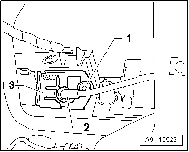
Caméra de recul -R189- : dépose et repose (Avant)
La caméra de recul -R189- est montée à côté du dispositif d'ouverture du hayon.
–
Mettre tous les consommateurs électriques hors circuit.
–
Retirer la clé de contact.
Dépose
La caméra de recul -R189- est dotée d'un câble flexible. Les raccords destinés au câblage du véhicule se trouvent dans le hayon.
–
Déposer le revêtement inférieur de capot arrière → Carrosserie - Travaux de montage Intérieur; groupe de rép.70.
–
Dévisser la vis -1- (4 Nm).
–
Retirer la tôle de fixation -3-.
La caméra de recul -R189--2- est calée dans l'étrier de poignée.
–
Extraire la caméra de recul -R189--2- de l'étrier de poignée avec un outil approprié.
Système de caméra de recul : calibrage
Après des travaux de remise en état du véhicule, il peut s'avérer nécessaire de procéder à un nouveau calibrage du système de caméra de recul. C'est notamment le cas après :
t
La dépose et la repose de la caméra de recul -R189-
t
Le remplacement du calculateur de système de caméra de recul -J772-
t
Des travaux de réparation liés à un accident de la circulation au niveau du hayon/capot de coffre
t
Des travaux de réparation sur l'essieu arrière
Travaux préliminaires
outillage spécial, contrôleurs, appareils de mesure et auxiliaires nécessaires
t
Système de diagnostic embarqué, de métrologie et d'information -VAS 5051B-
t
Dispositif de calibrage -VAS 6350-
t
Mesureur de distance au laser -VAS 6350/2-
Travaux préparatoires
Pour procéder au calibrage, le véhicule doit reposer sur une surface solide et plane. Pendant la mesure, personne ne doit se trouver à l'intérieur du véhicule. Ne pas déplacer le véhicule et ne pas ouvrir ou fermer les portes du véhicule pendant la mesure. Le hayon est fermé.
–
Raccorder le → système de diagnostic embarqué, de métrologie et d'information VAS 5051
–
Amener le capteur d'angle de braquage -G85- en position 0 (roues en ligne droite).
Vue d'ensemble du dispositif de mesure monté (berline)
1 - Fixation centrale de roue -VAS 6350/1-
2 - Fixation centrale de roue -VAS 6350/1-
3 - Équerre à droite
q
Support du mesureur de distance au laser -VAS 6350/2-
4 - Pied en matière plastique
q
Trois au niveau du soubassement du dispositif d'étalonnage -VAS 6350/4-
q
Réglable pour l'ajustage de la position horizontale du dispositif de calibrage -VAS 6350/4-
5 - Laser linéaire -VAS 6350/3-
q
Activation et désactivation → Notice d'Utilisation
6 - Mesureur de distance au laser -VAS 6350/2-
q
Consignes d'utilisation → Notice d'Utilisation
7 - Niveau à bulle sur le dispositif d'étalonnage -VAS 6350/4-
q
Permet de contrôler la position horizontale du dispositif de calibrage -VAS 6350/4-
8 - Angle gauche
q
Support du laser télémétrique -VAS 6350/2-
9 - Dispositif de calibrage -VAS 6350/4-
q
Entre les équerres du dispositif d'étalonnage -VAS 6350/4- et les griffes de centre de roue -VAS 6350/1-, -cote A- = 1,47 m à 1,90 m
Vue d'ensemble du dispositif de mesure monté (Avant)
1 - Fixation centrale de roue -VAS 6350/1-
2 - Fixation centrale de roue -VAS 6350/1-
3 - Équerre droite
q
Support du laser télémétrique -VAS 6350/2-
4 - Pied en matière plastique
q
Trois au niveau du soubassement du dispositif d'étalonnage -VAS 6350/4-
q
Réglable pour l'ajustage de la position horizontale du dispositif de calibrage -VAS 6350/4-
5 - Laser linéaire -VAS 6350/3-
q
Activation et désactivation → Notice d'Utilisation
6 - Mesureur de distance au laser -VAS 6350/2-
q
Instructions → Notice d'utilisation
7 - Niveau à bulle sur le dispositif d'étalonnage -VAS 6350/4-
q
Permet de contrôler la position horizontale du dispositif de calibrage -VAS 6350/4-
8 - Équerre gauche
q
Support du laser télémétrique -VAS 6350/2-
9 - Dispositif de calibrage -VAS 6350/4-
q
Entre les équerres du dispositif d'étalonnage -VAS 6350/4- et les griffes de centre de roue -VAS 6350/1-, -cote A- = 1,47 m à 1,90 m
Montage et ajustage du dispositif d'étalonnage -VAS 6350/4-
–
Vérifier le cercle de perçage des jantes.
–
Équiper les griffes de centre de roue -VAS 6350/1-.
–
Fixer à cet effet sur chaque griffe de centre de roue -VAS 6350/1- trois adaptateurs de boulons de roue sur le cercle de perçage.
–
Mettre en place les palettes sur les deux griffes de centre de roue -VAS 6350/1- et les fixer à l'aide de la vis de calage.
–
Mettre en place les griffes de centre de roue -VAS 6350/1- sur les boulons de roue des roues arrière.
Durant ce processus, les griffes de centre de roue -VAS 6350/1- sont positionnées et maintenues dans les adaptateurs par les « joints toriques ».
Nota
Mettre en place les griffes de centre de roue -VAS 6350/1- sur les roues de manière sorte que les « boulons de roue antivol » éventuellement montés ne soient pas solidaires de la griffe de centre de roue -VAS 6350/1-.
–
À l'aide des vis de calage, régler les palettes de manière à ce qu'elles puissent bouger librement, juste au-dessus du sol.
Veiller à ce que les palettes soient facilement manœuvrables.
–
Positionner le dispositif d'étalonnage -VAS 6350/4- derrière le véhicule en respectant un écart de 1,47 m à 1,90 m par rapport aux roues arrière, voir la -cote A- de la vue d'ensemble - berline → ancre / Avant → ancre.
–
Amener le dispositif d'étalonnage -VAS 6350/4- en position horizontale.
–
Tourner à cet effet les pieds en matière plastique situés sous le dispositif d'étalonnage -VAS 6350/4- de manière à ce que la bulle d'air du niveau se trouve exactement au centre -flèche-.
ATTENTION !
Veiller à ce qu'aucun reflet lumineux ne parvienne sur le dispositif d'étalonnage -VAS 6350/4- !
Les reflets lumineux gênent la reconnaissance d'images de la caméra de recul -R189- et peuvent même empêcher la réalisation du calibrage.
–
Mettre en marche le laser ligne -VAS 6350/3--1- du dispositif d'étalonnage -VAS 6350/4- et positionner l'ensemble du dispositif -VAS 6350/4- de manière à ce que le faisceau laser du laser ligne -VAS 6350/3- touche l'arrière du véhicule au niveau du milieu des anneaux Audi.
Berline
Avant
–
Vérifier que les anneaux Audi sont centrés à l'arrière du véhicule. Rectifier le faisceau laser en conséquence.
–
Mettre en circuit le mesureur de distance au laser -VAS 6350/2- en appuyant sur la touche ON.
L'affichage suivant apparaît à l'écran ; le laser se met en marche.
–
Tenir le laser télémétrique -VAS 6350/2--2- à ras de l'équerre d'un côté du dispositif d'étalonnage -VAS 6350/4-, comme indiqué sur la figure ; le laser télémétrique -VAS 6350/2- doit être bien appliqué contre l'équerre.
–
Veiller à ce que le rayon laser du mesureur de distance au laser -VAS 6350/2- vise la partie inférieure élargie de la palette -1-.
Si tel n'est pas le cas, corriger la position des palettes à l'aide des vis de calage de la griffe de centre de roue -VAS 6350/1-.
–
Maintenir d'une main le laser-mètre -VAS 6350/2- dans l'équerre du dispositif d'étalonnage -VAS 6350/4-, le faisceau laser étant visible sur la palette.
–
Actionner à présent brièvement la touche ON pour la mesure de distance.
Affichage à l'écran
–
Noter la valeur relevée.
–
Réitérer le processus de mesure pour l'autre roue arrière située de l'autre côté du dispositif d'étalonnage -VAS 6350/4- en procédant de la même manière.
La valeur relevée doit être identique pour les deux côtés.
Si tel n'est pas le cas :
–
Ajuster le dispositif d'étalonnage -VAS 6350/4- jusqu'à ce que les valeurs soient identiques des deux côtés.
En ajustant le dispositif d'étalonnage -VAS 6350/4-, veiller à ce que le faisceau du laser ligne -VAS 6350/3- du dispositif d'étalonnage -VAS 6350/4- soit toujours dirigé sur le milieu des anneaux Audi et à ce que l'indicateur du niveau à bulle reste bien centré. Corriger l'ajustement le cas échéant.
–
Mesurer la hauteur du dispositif d'étalonnage -VAS 6350/4-, cote -H- (rebord supérieur du tableau - plancher).
Entrer l'écart et la hauteur mesurés dans le système de diagnostic embarqué, de métrologie et d'information -VAS 5051B- en « millimètres ».
Procédure du calibrage
Dans le système de diagnostic embarqué, de métrologie et d'information -VAS 5051B-, sélectionner les « Fonctions assistées ».
–
Sélectionner dans le menu « Sélection du véhicule » les données correspondantes au véhicule.
–
Sélectionner « système de caméra de recul ».
–
Sélectionner les « Fonctions ».
–
Sélectionner « Calibrage ».
À partir de cette étape, le système de diagnostic embarqué, de métrologie et d'information -VAS 5051B- guide le mécanicien dans le processus d'étalonnage.
ATTENTION !
Veiller à ce qu'aucun reflet lumineux ne parvienne sur le dispositif d'étalonnage -VAS 6350/4- !
Les reflets lumineux gênent la reconnaissance d'images de la caméra de recul -R189- et peuvent même empêcher la réalisation du calibrage.
http://audiforum.us/mmi/6043-retrofit-rear-view-camera-q7.html
I have just installed the module and camera in Q7 and when putting the reverse gear the tv tuner comes out with the side picture of the car with parking sensors.
What is it wrong?
I cant calibrate the camera without getting the vision....
i sort out this problem.
after calibrating the camera the coding also has to be done.
so q7 reversing camera is no longer a problem
to code the camera enter
address 07 with your vag com
and you have to add the value +32768
then enter address 76 and value 0200006 will show up
you have to add 2, 0x?xxxx where the question mark so you should get 02200006.
after that you have to go to audi dealer to calibrate the camera.
be aware that only few dealers can do it as the special calibration system is required and not every dealer has that in their work shop
The calibration is only required on the A6/A8/Q7/R8, and if you use the genuine Audi parts.
http://audiforum.us/mmi/5224-retrofit-rear-camera-a8-6.html
Reverse Parking Camera Retrofit for an Audi A8
This retrofit guide is based on having the TV module already fitted.
Parts Required
Can gateway 4L0 907 468
Reversing Camera 4E0 980 551
Securing arm for camera 4E0 980 553B
Seal for Camera 4E0 980 555
Wiring harness (Try Kufatec, or make your own)
Flat contact housing for connecting to the control module 4E0 972 144
Flat contact housing for connecting to the power lead of the camera 1J0 973 119
Camera Control unit 4E0 910 441
FAKRA Cables x2 (Kufatec)
Boot lid switch 4E0 827 565 B
Guide piece right hand side 4E0 971 446C
Grommet rear lid right 4E0 971 876 C
Grip Rail painted (This depends on the year of your car) for the single grill face lift model 4E0 827 576 F GRU
Gasket for grip rail 4E0 827 594 A and 4E0 827 599 A
Pin-out for the Reversing camera control unit
Pin 39 CAN BUS Low (Convenience) - This could be connected to pin A7 on the parking aid control unit Wire colour Orange/Brown
Pin 40 CAN BUS HIGH (Convenience) - This could be connected to pin A14 on the parking aid control unit Wire colour Orange/Green
Pin 43 Terminal 30 - To Fuse box
Pin 44 Terminal 31 - Chassis ground
Pin 47 Terminal 31 to camera - To Camera pin 2
Pin 48 Reversing camera power supply - To Camera pin 1
First stage was to replace the can-gateway with the reverse camera compatible version. Before you replace the gateway, make a note of the all the coding options on the current gateway, as you will not be able to copy and past the long code to the new gateway. As shown below
To replace the gateway, you must remove the glovebox, this is held in place with three bolts at the top of the glove box, 1 screw behind the cd-changer, (you will need the Audi removal keys to slide the changer out) another bolt is behind storage insert next to the cd-changer, and the final bolt is underneath the glovebox.
Once the glovebox is lowered, the gateway is removed by removing the 2 bolts, unplug the fibre optic cable and the 26 pin connector. Fit the new gateway, and refit the glovebox and CD-Changer.
With vag-com connect to the can gateway, and re-enter all the options for your car. Once done connect to the can-gateway and clear all the fault codes and see if any re-appear. You may find that the can-gateway is in component protection, and this will need to be cleared by your local dealer.
Depending on where your going to mount the reversing camera module, you will need to make up a wiring harness. The harness I made up was about 2 meters long for +12 line and the ground wire, the FAKRA cable will also need to be the same length. The Ground, + 12v, Can-high and can-low wire will need to be about 1 meter in length, but again depends on where you locate camera module.
All the pins used to make up the wiring harness can be purchased from kufatec.
I first started on connecting the can-bus wiring, the rear parking module has the (Convenience)can-bus wiring and this module was located above the navigation DVD drive. You first need to remove the navigation drive from the cage, again you will need Audi removal keys to slide out the drive. You will then need to remove the two bolts holding the cage in place. The paring module is mounted on top of the cage.
The two wires you need are can-high (Orange/Green) can-low (orange/Brown) You can tap into the wires by ether soldering directly onto the pins of the plug of the parking module or strip some of the sheath away connect that way. At this point it's best to leave the navigation cage off as it make it easier to get access to run the rest of the wiring harness.
Connect the power wire to a spare connector in the fuse holder (the connecters for the fuse box can again be purchased from kufatec) you could also just tap into one of the power wires going into the fuse box. Connect the ground wire to the earth point on the chassis, this should be located near the fuse box.
The next stage is to run the wire into the boot lid, this was done by running the wire through the rubber grommet as shown in the picture below, you could this by running it through the same hole in the grommet, but this appeared to be a lot of work and I did not want to disturb the current seal, so I made another hole in the grommet, which was smaller that the wire and fed the wire through that.
Near the boot piston there is a small plastic cover, remove this and you should be able to see the wire and pull it through. Once the wire has been pulled through all the way push the rubber grommet back in place. You can then refit the navigation mount & drive.
You need to remove the internal boot trim cover, for this you will need to remove the 4 screws holding the toolbox in place, you will need need to remove the two grip handles, these are held in place by two screws, but these are hidden behind a plastic cover which folds down. The boot lid cover can then be unclipped, being carefully to disconnect the plugs going into light and the boot closer switch.
Once the cover is removed you will have full access to remove the grip rail. First remove the plastic cover which covers the locking mechanism, then remove the 2 tox head screws holding it in place, and pull the mechanism out of the grip rail. Disconnect the wires going into the number plates lights, and the boot switch. Remove the 4 nuts holding the grip rail, and remove the grip rail.
Remove the number plate lights from the old grip rail. Fit the lights and the boot switch, then fit the foam seals for the parking camera & the grip rail. Fit the parking camera, and camera securing clamp. Refit the grip rail and the locking mechanism, also reconnect the wires to the lights & boot switch.
Run the power wires & FAKRA cable through the grommets & plastic tubing, attach tubing the (plastic conduit) push the lower rubber grommet into the quarter panel. Remove the plastic cover in the boot lid and feed the wire into the boot lid, push the rubber grommet into the boot lid. Fit the plastic connector over the FAKRA cable, then wire up the ends of the power cable and fit into the plug.
Connect the power cable and the FAKRA cable to the camera, and secure the cables. Refit the boot trim remembering to connect the boot switch & light.
Disconnect the FAKRA cable going into the TV tuner, using a kufatec lead extend the cable to the camera control module, then run a new FARKA cable from the control module to the TV tuner. connect the FAKRA cable from the camera to the control module, and connect the 54pin connector. If you isolated the camera module at the fuse box, inset a 5amp fuse.
That should have completed the hardware installation of the retrofit. Using vag-com connect to the can-gateway and enable the 6c Back-up Cam, then clear any fault codes, as the only one you should have on the can gateway module is component protection.
In vag-com select 6c Back-up Cam
Enter the correct coding
Select 07-Control head
Select Adaptation
Select channel 01
add +32768 to the current value
Select TEST
Select Save
Select 76-Park Assist
Select Coding
Add +2 to 0x?xxxx
Select Do it
Installatgion should now be complete.
In case you don't have the rear parking module, you can use the Comfort System Control Module (4F0907289G) (1) located in the right compartment of your trunk and tap into the CAN Gateway cable (2). It's a twisted pair. Orange/Green is CAN High and Orange/Brown is CAN Low.
To mount the Camera Control unit, I used two hanger bolts that I drilled into the car and then attached the unit to them.
After some driving with the camera, Component Protection kicked in hard. The instrument panel lit up like a Christmas tree with ABS, Brake, Airbag, EPC, the words "SAFE" and maybe a few other things. The climate control stopped working. The interior light would not turn on. The fuel gage showed "empty" and all kinds of other little issues popped up. But the car drove fine.
Just came back from the dealer. All issues were cleared up. The car is back to normal and everything still works (TV, Nav, AMI).
Hello I need help. I instaled reverse parking camera. Everything works fine, but I dont see "graphic" button and model car on left side.
Have you recoded the parking controller & mmi controller for the camera?
I am retrofitting the rear camera and active cruise, AMI and swapping the analogue TV for Hybrid at the same time.
I ordered the can gateway version 4E0 907 468 G as it supports the rear camera and Adaptive cruise control.
Audi UK and Germany are out of stock of version G so have substituted it with version H (A8Q - S8Q 2008 - 2009) instead.
When the dealer tried to clear the component protection, the car threw a wobbly about incorrect coding in the gateway and it simply refused to let the VAS unit save the coding of the modules found in the car.
As a consequence they told me they where unable to remove CP from AMI and Hybrid TV unit as the gateway didn't know they existed.
As it was Saturday, we ran out of time and dealer has booked me in on Tuesday for a 'thorough' investigation (god knows how much that is meant to cost!!!)
When I got home, I used Vag-Com, and the coding on the new module is very different to the old one, and the bit that seems to be causing the problems, the new module has no support for item 25 (immobiliser).
I recoded it to match the items selected on the old gateway and all seems fine.
Oddly, no CP on the AMI or the Hybrid TV , is this normal???
So what do I do? the car seems to function fine! Doesnt it matter that module 25 is not coded, it thrown no errors, but as it is not coded Vag-Com can't communicate with the module.
Any ideas?
God saves these Audi Services[-o<[-o<[-o<[-o<
first of all Ami and TV-tuner are some of few components that never go in C.P. and about the 25 Immobilizer is perfectly normal that it doesn't exist under 4LO GATEWAY because your Immo is now seen in 05 Acc/Start/Auth.module. I have the same Gateway see here the PN and the coding:
Address 19: CAN Gateway Labels: 4L0-910-468.lbl
Part No SW: 4L0 910 468 A HW: 4E0 907 468 H
Component: J533__Gateway H06 0060
Revision: 00H06000 Serial number: 0200J078188054
Coding: F5F9DF7F717E0E00
Shop #: WSC 00870 264 00001
What are the differences among the control units: 4E0 910 441 | 4F0 910 441 | 4L0 910 441.
Of course 4E=A8, 4F=A6, 4L=Q7.... but what is the main difference? Can 4F0/4L0 be used on the A8 ?
can any one tell me if the can gateway nr: 4F0 907 468 G works in my audi a8 , or i need the 4E0 907 468 G ... i so at page 7 , that i need 4L0-910-468 ????????
can any one advice me ?
because i have to buy a can gateway for my car because i installed a tv tuner and a back up camera and i have some problems with camera ..is not working and if i understand well i have to change olso a gateway.
please i need help.
definately the right one is: 4L0 907 468 B SW: 4L0 910 968 A
if you need it just send me a private message
Keep in mind this is on an A8 that already has all the parking sensors. Not sure what to do for those without other then to retrofit that system as well.
I will update this post as I go along with this project with things I find etc. Right now at this post is purely in theory mode and based on collections of information I've found on the web in many different places that I've compiled into this one location. Result will vary input and commets are welcome.
I wont start with actual install proceedures as I will provide those once the project is fully underway.
Right now I am in parts and wiring aquire mode. (note I haven't even taken delivery of my A8 yet, that will happen this afternoon)
I am going to be doing this work on a 2006 A8L
The following parts information is from TDIAvant on Audiforums:
Parts Required
Can gateway 4L0 907 468
This a newer can gateway that knows about the backup camera system.
Reversing Camera 4E0 980 551
Securing arm for camera 4E0 980 553B
Seal for Camera 4E0 980 555
Wiring harness (Try Kufatec, or make your own)
Flat contact housing for connecting to the control module 4E0 972 144
Flat contact housing for connecting to the power lead of the camera 1J0 973 119
Camera Control unit 4E0 910 441
This will be the central hub where everything comes together.
FAKRA Cables x2 (Kufatec)
Boot lid switch 4E0 827 565 B
Guide piece right hand side 4E0 971 446C
Grommet rear lid right 4E0 971 876 C
Grip Rail painted (This depends on the year of your car) for the single grill face lift
model 4E0 827 576 F GRU
Gasket for grip rail 4E0 827 594 A and 4E0 827 599 A
FBAS Part Number: 4E0 035 729 A
======================
In addition those with out the TV system will need one more rather pricy item called a MMI Display Interface w/FBAS Video Input. From what I read this is a critical piece as opens the door for the MMI system to have video inputs. Those who already have the car equipped with a TV tuner system will already have this part.
TV tuner option Digital or Analog
Digital:
4E0 910 148 B
Analog:
4E0 919 146 OR 146A
Note from what I can tell the TV tuner piece is not really required to do the backup camera, only the FBAS MMI Interface.
Without the backup camera in the equation one could connect the TV tuner directly with the FBAS MMI Interface. This would give you TV capabilities and auxilary input capabilities.
It required not only putting the device on the MOST ring it will also require several standard wire and one coax connection as well.
=========================
Back to doing all of this with the backup camera. When the Camera control unit is in the equation (4E0 910 441) this will serve up as the central hub for all video inputs in the car. This controller is very much like a video receiver is for home theaters. It makes sense as when you put the car in reverse or turn on the parking sensors this will automatically switch video inputs to the camera. In the photo below you'll see that the camera control unit has 3 coax inputs going to it. The green line goes to the FBAS module, one is for the TV Tuner and other AV devices, and the last is for the backup camera.
AV/TV tuner--> Backup Camera Module
Backup Camera --> Backup Camera Module
FBAS Module <--- Backup Camera Module
MP3 CD changer for those that want to know:
4E0 057 110 C --CD Changer that plays MP3's
4E0 057 111 F --CD Changer that cannot play MP3's
4E0 910 111 E --CD Changer that cannot play MP3's
Its over $400 at the dealer...
4L0 907 468 or 4L0 907 468B work. 2008 Q7's and A8's come with 4L0 907 468B
4E0 907 468G would work as well and would be required if you have distance cruise control.
Those of you with distance cruise control that plan this mod be very careful in the parts you buy to keep compatibility with this feature.
http://wiki.ross-tech.com/wiki/index.php/Audi_A6_%284F%29_Back-Up_Camera
-
•?0x0xxx: Manufacturer
-
◦1 = Audi
-
•x0?0xxx: Trailer & Parking System
-
◦+1 = Trailer Hitch installed
-
◦+2 = Optical Parking System installed
-
•x0x0?xx: Camera Height
-
◦0 = Camera Height 1
-
◦1 = Camera Height 2
-
◦2 = Camera Height 3
-
◦3 = Camera Height 4
-
◦4 = Camera Height 5
-
◦5 = Camera Height 6
-
◦6 = Camera Height 7
-
◦7 = Camera Height 8
-
•x0x0x??: Model
-
◦01 = Audi Q7 (4L)
-
◦02 = Audi A8 (4E) Short Wheel Base
-
◦03 = Audi A8 (4E) Long Wheel Base
-
◦04 = Audi A6 (4F) Sedan / Rest of World (RoW)
-
◦05 = Audi A6 (4F) Wagon/Avant
-
◦06 = Audi A4 (8K) Sedan
-
◦08 = Audi A5 (8T) Coupé
-
◦12 = Audi R8 (42)
-
◦14 = Audi A6 (4F) Sedan / China (CHN)
-
Security Access
-
•22351 = Adaptation Enabling (e.g. Back-Up Camera Calibration)
Special Procedures
Back-Up Camera Calibration
After performing service work, the calibration has to be performed too. In detail this is the case after:
-
•Removing and Installing Rear View Camera (R189)
-
•Replacing Rear View Camera System Control Module (J772)
-
•after repair work performed on rear lid following an accident
-
•after a vehicle alignment
-
•after performing a repair at front or rear axle
Prerequisites:
-
•Calibration Device (VAS 6350) and Distance Laser (VAS 6350/2) positioned as described in the factory repair manual.
-
•Vehicle must be standing on a firm and even surface.
-
•Make sure no persons are being/working in/on the vehicle while performing the calibration.
-
•Do not move the vehicle and do not operate the vehicle doors while performing the calibration.
-
•Rear Lid must be closed.
-
•Front Wheels straight, Steering Angle Sensor (G85) close to 0.0 °.
-
•Ignition must be ON, Engine must NOT be running, you may connect a charger to keep the system voltage up.
-
•Back-Up Camera active and the MMI shows Back-Up Camera Video Signal.
-
•Make sure you do NOT have light reflections on the Calibration Device (VAS 6350).
-
•For vehicles with Level Control, set the Hight to automatic.
[Select]
[6C - Back-Up Camera]
[Security Access - 16]
Enter 22351, to enable the adaptation.
[Adaptation - 10]
Channel 005
[Read]
500 mm is the basis value of channel 005. Measure the heights between the Calibration Device (VAS 6350) and the surface (e.g. 80 mm), add 500 mm to it and enter the final value as new value (e.g. 500 + 80 = 580 mm).
[Test]
[Save]
Channel 004
[Read]
20000 mm is the basis value of channel 004, 3002 mm is the axle distance. Measure the Distance between the Calibration Device (VAS 6350) and the rear axle (e.g. 1500 mm), and subtract it from 20000 mm minus 3002 mm enter the final value as new value (e.g. 20000 - 3200 - 1500 = 15498 mm).
[Test]
[Save]
Channel 001
[Read]
To save your above adaptation save a new value of 1 to channel 001.
[Test]
[Save]
[Done, Go Back]
Now double check the calibration status.
[Meas. Blocks - 08]
Block 130
[Go!]
Block 130 Field 3 (Calibration Status)
Specification: 0x0000 (Calibration Successful)
[Done, Go Back]
[Close Controller, Go Back - 06]
Notes on retrofitting Audi Parking System Advanced rear-view camera Audi A6 (4F/C6) (also relevant for A4/A5/Q7/A8)
1.6.2008 (updated 14.3.2010) - Note: This article covers my notes on a potential retrofit project that I have not performed myself, only researched online and from some other sources, so I can not say if my notes are fully accurate or not. However, I think this may be a good starting point for someone interested in this type of project. I have mainly researched A6, but much of this is likely relevant with Q7/A8 MMI 2G High too (as well as A4/A5 with MMI 2G DVD navigation). MMI 3G, which has been shipping on Audis since late 2008/mid-2009 depending on model, has somewhat different connections, a few notes on that in the end.
---
UPDATE 14.3.2010:
Instructions for building a rear-view camera calibration board and running the calibration here:
AudiForum.us: Rear view camera in MMI 3G (page 3)
http://audiforum.us/mmi/13156-rear-view-camera-mmi-3g-3.html
---
UPDATE 16.10.2008:
For information on retrofitting actual parking sensors, other parts of the Audi Parking system, see:
Notes on retrofitting parking sensors/Audi Parking System in Audi A4/A5/A6 etc. (by LoCal)
http://a6retrofit.tripod.com/articles/audiparkingsystem.html
---
As background I must stress that my car came with the optional Audi Parking System Plus (both rear and front sensors as well as optical graph display on MMI) and being model-year 2007, had the rear-view camera software upgrade already built-in. I also have MMI High, which is of course required. These make it easier to consider this upgrade, because pretty much everything else but the camera is already in the car. (Kufatec.de does sell a full upgrade kit for cars without Audi Parking System Plus, with the eight sensors and all, but these notes do not cover that eventuality - which would definitely be a lot more work than just installing the rear-view camera. Kufatec can even upgrade your car from the monochrome MMI basic to full colour MMI High, but that is even more work and costlier.)
Being a pretty complete base for installing the rear-view camera upgrade, one thing that my car does not have, though, is the TV module. Surprisingly (or not), this plays an important role in the Audi Parking System Advanced installation and would add a work intensive extra step and cost to a retrofit. Let me explain:
The Audi MMI system is based on a MOST fiber-optic ring (thick optical cabling) that travels from component to component (main/front unit behind glove compartment to telephone under driver's seat to amplifier and radio and navigation in the trunk etc.) inside the car. In addition, a traditional diagnostics signal line (green wire) goes from component to the next as well as power and ground of course from the fuse boxes and ground lugs. This is a pretty sophisticated setup, because it can transmit data and audio digitally over the MOST link allowing separation of components throughout the car and good expandability instead of having to build almost everything inside one box as is the case with the monolith sat-nav radios of previous generations or rely on analogue signals for things like audio that may degrade quality.
One thing this MMI generation cannot do, however, is transmit video over the MOST optical cable. There isn't enough bandwidth, I guess. So video is handled traditionally: the TV module in the trunk (if installed) sends it picture via a composite video cable (yeah, just composite) to the main unit behind the glove compartment in the front. Here's the catch: Only with TV module (or rear-view camera or both), does the main unit have a composite video input connector as well as the composite video cabling circumnavigating the car. So, unless the TV module was ordered from factory (or retrofitted successfully), the rear-view camera too is without a composite video connection to latch into. In fact, when both TV module and rear-view camera are ordered from factory, they are installed serially: one single composite video line travels via TV module and rear-view camera module (which are located in opposing sides of the trunk) and ends up at the main unit in the front of the car.
So, without a TV module, my car was bound to have shipped without this composite video connection (so called FBAS input, coloured green) - which I later confirmed myself to be the case. First thing a rear-view camera retrofit requires, then, is the changing of the main/front MMI module behind the glove-compartment and routing of a cable from the front to the right side of the trunk in the back where the rear-view camera module would come (see my Bluetooth retrofit on this site for information on how to route cables from the front to the back under the flooring). Luckily Kufatec is able to provide a used main unit with composite for a reasonable price, but you will still need your dealer to remove possible Component Protection that may occur when the used main unit is installed in a new car (this is a built-in protection against theft of components) - this protection can not be removed with just VAG COM, it can only be done by a dealer with online connection to Audi (and then only if the component has not been reported stolen).
If you need instructions on how to remove the glove compartment, see my report on the Bluetooth retrofit elsewhere on this site (go to the index to find the link). See also my notes on TV module retrofit on this site for more information and links on fitting a composite video enabled MMI main/front module.
Once this thing is out of the way, most of the rest happens in the trunk area of the car (not all, though), and is more directly related to the actual installation of the rear-view camera. Here is my understanding of the process (for which Kufatec is also able to provide an installation kit with instructions, see Kufatec.de for Komplett-Set APS Advance - Rückfahrkamera Audi A6 4F):
The rear-view camera consists basically of two components and cables connecting them to each other and the main MMI unit in the front (and also the TV module if that is in the car). The first component is the actual camera attached to the trunk opening button/rear license plate lighting fixture and the second is the rear-view camera control box and attached plastic holder.
The rear-view camera control box goes to behind the covers of the right side of the trunk (when looking forward), below the fuse box that is there - you can see this general area when you remove the right side hatch in the trunk that is there to access the fuse box and the tools stored there. However, to really work in this area you need to remove the right side wall coverings of the trunk, see my report on Bluetooth retrofit elsewhere on this site for notes on how to remove the left side trunk coverings, the right side should be similar.
From there, the power (red cable) and ground (brown cable) are routed to the above fuse box and ground lug (see my reports on Bluetooth and DVD navigation retrofits on this site for more on power connections in general). There are also black/yellow and black/white cables that connect to the CAN bus, as well as a separate Cangateway 4L0 box that needs to go somewhere. I believe the CAN cables connect to the existing parking aid control box CAN cabling or something like that, but Kufatec does provide more instructions with the kit. The Cangateway 4L0 box, on the other hand, goes to behind the glove compartment where it replaces the existing Cangateway box with a version that supports the rear-view camera - you need to record existing Cangateway settings with VAG COM before replacing the module and restore them afterwards manually. (Apparently if your car has adaptive cruise control affects this process somehow, but one would have to ask Kufatec for more information.) See also the link at the end of these notes for more on this subject (on an A8).
Finally, two or three video cables go to different directions: one cable (green connection) goes to the front of the car to the main/front/display MMI component, this is the FBAS component video cable, and one cable (grey connection) goes up the trunk door to the camera. If the TV module is fitted, the third cable (brown connection) goes under the trunk to the left side component rack and the TV module there. Some people who already have the TV module in the car have opted to retrofit the rear-view camera module on the left side instead of its true place on the right, because then they can just use the existing component video cable there by removing it from the TV module and connecting it to the rear-view camera module - and then completing the connections by connecting the rear-view module and TV module component video connections with a short cable.
In the trunk door the entire fixture containing the license plate lights and trunk opening handle is replaced by a new one that contains the camera. Then the cabling is routed up the trunk door (and down the rear window pillar on Avant models) to the rear-view camera control box on the right side of the trunk - and that is pretty much it.
Several kinds of codings are required for the car to recognize the rear-view camera; Kufatec apparently lists these in their instructions. There is also the possibility of Component Protection kicking in, so a visit to an official maintenance shop might be required to clear out those after installation. Also, in addition to the camera image, the rear-view camera provides graphical guidelines for parking. They work without calibration, but for true accuracy some sort of laser-guided calibration is required, or so I've been told. This can probably be performed by your Audi dealer.
A really good posting on this for Audi A8 here, a similar process in many ways as in A6 (but not entirely the same of course):
Reverse Parking Camera Retrofit for an Audi A8
http://navplus.us/forums/showthread.php?t=5224&page=6
Also, some information on the calibration and coding process here:
http://wiki.ross-tech.com/index.php/Audi_A6_%284F%29_Back-Up_Camera
---
UPDATE 25.1.2009 / 27.1.2009:
Slightly related to his issue...
In the U.S. the rear-view camera is also available without front parking sensors. This has caused interesting issues when updating U.S. MMI software to European versions, e.g. on the A5/S5 rear-view camera stops working after 3 seconds when using an U.S. car with European MMI software. The question covered here and my notes below:
Audi S5 Rear Camera PROBLEM after update MMI !!! HELP !!!
http://audiforum.us/mmi/9225-audi-s5-rear-camera-problem-after-update-mmi-help.html
This is an interesting question, probably rooted in the fact that the reverse camera option is different in the U.S. compared to Europe.
In (all of, I believe) Europe the reverse camera is part of a Audi Parking System Advanced package, that includes rear and front sensors, the camera and associated operator button in the dashboard to activate the system. The U.S. version in A5 only includes the rear sensors and camera and activates on reverse only (the Euro version also activates on reverse in addition to the dashboard button). There is no rear-sensors only with camera option in Europe.
It wouldn't surprise me if the software treated these systems differently or even if there are hardware level differences between them (the U.S. system being more like the APS basic in Europe with just rear sensors and no button). This might result in the camera being activated, but disengages soon because the car lacks the dashboard button and front sensors (maybe it just disengages because it seems like an error situation) that should be there.
Hopefully this is just a matter of figuring out what coding changes are needed and not a fundamental incompatibility with the software.
This can be cured with the following settings changes, then European software should work fine (see elsewhere on this site, e.g. A5 VAG COM article, for more on how to access the hidden menu):
Hidden Menu >> DIAG SETTINGS >> APK 0x01, 0x0B, 0x0C
Uncheck: APS (front)
Uncheck: APS (rear)
Check: APS
If that doesn't help, revert back to U.S. software.
---
UPDATE 16.7.2009:
3G rear parking camera
http://audiforum.us/mmi/12049-3g-rear-parking-camera.html#post73833
On the MMI 3G, according to "craigyb", the rear-view camera connects to the blue 12 pin connector on the MMI 3G head-unit, to pins 11 (FBAS +) and 5 (FBAS -). TV FBAS connects to a green FBAS connector on the head-unit.
---
UPDATE 12.12./13.12.2009:
For the Finnish reading audience, hpu's rear-view camera retrofit report here:
Peruutuskameran jälkiasentaminen Audi A6 (4F/C6) (osin myös A4/A5/Q7/A8) (by hpu)
Original link:
UltimateVW.com: Kaikkea Audi A6:sta (4F) (sivu 107)
http://www.ultimatevw.com/keskustelu/index.php?cmd=aihe&id=3715&sivu=107


B C et D = connecteur FBAS antenne 6Q0 035 576 K
cable 000 098 692


http://www.audisport-iberica.com/foro/index.php?/topic/217155-fabricar-cables-coaxiales-tipo-fakra/
Installation de la caméra de recul en seconde monte

